SolidWorks: Make Drawing from Part/Assembly
This article has not been updated recently and may contain dated material.
This article will walk you through the steps of turning a part or assembly into drawings.
Making a Drawing from Part/Assembly
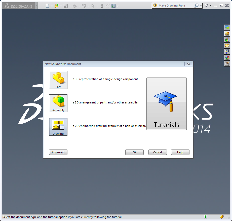
1. Select New SolidWorks Document.
2. Click Drawing and click OK.
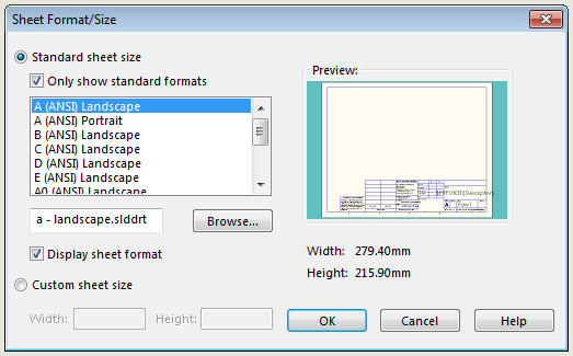
3. You will then be prompted to choose your sheet size and orientation. Select desired size and orientation from the drop down menu and click OK.
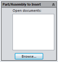
4. When the new document window opens, select Browse under the Part/Assembly to Insert section on the left-hand bar and select a part or assembly you wish you insert from the file browser.
5. Once you have placed your first drawing you can move your mouse to the right, left, top, or bottom and SolidWorks will insert the corresponding view to that location.
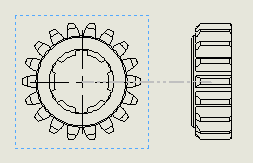
6. You can also insert an Isometric view by moving your mouse away from the drawing at a 45 degree angle.
Referenced from: SolidWorks
12744
12/19/2023 3:51:06 PM